Build123d is a python-based, parametric, boundary representation (BREP) modeling framework for 2D and 3D CAD. It’s built on the Open Cascade geometric kernel and allows for the creation of complex models using a simple and intuitive python syntax. Build123d can be used to create models for 3D printing, CNC machining, laser cutting, and other manufacturing processes. Models can be exported to a wide variety of popular CAD tools such as FreeCAD and SolidWorks.
Build123d could be considered as an evolution of CadQuery where the somewhat restrictive Fluent API (method chaining) is replaced with stateful context managers - e.g. with blocks - thus enabling the full python toolbox: for loops, references to objects, object sorting and filtering, etc.
Overview
build123d uses the standard python context manager - e.g. the with statement often used when
working with files - as a builder of the object under construction. Once the object is complete
it can be extracted from the builders and used in other ways: for example exported as a STEP
file or used in an Assembly. There are three builders available:
BuildLine: a builder of one dimensional objects - those with the property of length but not of area or volume - typically used to create complex lines used in sketches or paths.
BuildSketch: a builder of planar two dimensional objects - those with the property of area but not of volume - typically used to create 2D drawings that are extruded into 3D parts.
BuildPart: a builder of three dimensional objects - those with the property of volume - used to create individual parts.
The three builders work together in a hierarchy as follows:
with BuildPart() as my_part:
    ...
    with BuildSketch() as my_sketch:
        ...
        with BuildLine() as my_line:
            ...
        ...
    ...
where my_line will be added to my_sketch once the line is complete and my_sketch will be
added to my_part once the sketch is complete.
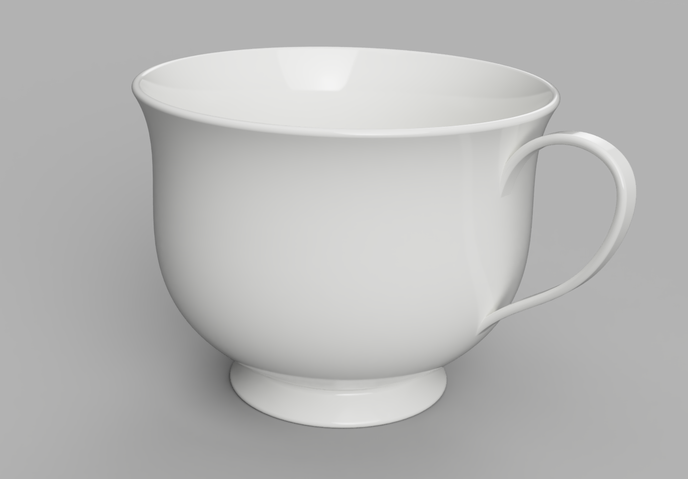
As an example, consider the design of a tea cup:
from build123d import *
from ocp_vscode import show

wall_thickness = 3 * MM
fillet_radius = wall_thickness * 0.49

with BuildPart() as tea_cup:
    # Create the bowl of the cup as a revolved cross section
    with BuildSketch(Plane.XZ) as bowl_section:
        with BuildLine():
            # Start & end points with control tangents
            s = Spline(
                (30 * MM, 10 * MM),
                (69 * MM, 105 * MM),
                tangents=((1, 0.5), (0.7, 1)),
                tangent_scalars=(1.75, 1),
            )
            # Lines to finish creating ½ the bowl shape
            Polyline(s @ 0, s @ 0 + (10 * MM, -10 * MM), (0, 0), (0, (s @ 1).Y), s @ 1)
        make_face()  # Create a filled 2D shape
    revolve(axis=Axis.Z)
    # Hollow out the bowl with openings on the top and bottom
    offset(amount=-wall_thickness, openings=tea_cup.faces().filter_by(GeomType.PLANE))
    # Add a bottom to the bowl
    with Locations((0, 0, (s @ 0).Y)):
        Cylinder(radius=(s @ 0).X, height=wall_thickness)
    # Smooth out all the edges
    fillet(tea_cup.edges(), radius=fillet_radius)

    # Determine where the handle contacts the bowl
    handle_intersections = [
        tea_cup.part.find_intersection(
            Axis(origin=(0, 0, vertical_offset), direction=(1, 0, 0))
        )[-1][0]
        for vertical_offset in [35 * MM, 80 * MM]
    ]
    # Create a path for handle creation
    with BuildLine(Plane.XZ) as handle_path:
        path_spline = Spline(
            handle_intersections[0] - (wall_thickness / 2, 0),
            handle_intersections[0] + (35 * MM, 30 * MM),
            handle_intersections[0] + (40 * MM, 60 * MM),
            handle_intersections[1] - (wall_thickness / 2, 0),
            tangents=((1, 1.25), (-0.2, -1)),
        )
    # Align the cross section to the beginning of the path
    with BuildSketch(
        Plane(origin=path_spline @ 0, z_dir=path_spline % 0)
    ) as handle_cross_section:
        RectangleRounded(wall_thickness, 8 * MM, fillet_radius)
    sweep()  # Sweep handle cross section along path

assert abs(tea_cup.part.volume - 130326) < 1

show(tea_cup, names=["tea cup"])

Note
There is a Discord server (shared with CadQuery) where you can ask for help in the build123d channel.
Table Of Contents
- Introduction
- Installation
- Key Concepts (builder mode)
- Key Concepts (algebra mode)
- Introductory Examples
- 1. Simple Rectangular Plate
- 2. Plate with Hole
- 3. An extruded prismatic solid
- 4. Building Profiles using lines and arcs
- 5. Moving the current working point
- 6. Using Point Lists
- 7. Polygons
- 8. Polylines
- 9. Selectors, Fillets, and Chamfers
- 10. Select Last and Hole
- 11. Use a face as a plane for BuildSketch and introduce GridLocations
- 12. Defining an Edge with a Spline
- 13. CounterBoreHoles, CounterSinkHoles and PolarLocations
- 14. Position on a line with ‘@’, ‘%’ and introduce Sweep
- 15. Mirroring Symmetric Geometry
- 16. Mirroring 3D Objects
- 17. Mirroring From Faces
- 18. Creating Workplanes on Faces
- 19. Locating a workplane on a vertex
- 20. Offset Sketch Workplane
- 21. Create a Workplanes in the center of another shape
- 22. Rotated Workplanes
- 23. Revolve
- 24. Loft
- 25. Offset Sketch
- 26. Offset Part To Create Thin features
- 27. Splitting an Object
- 28. Locating features based on Faces
- 29. The Classic OCC Bottle
- 30. Bezier Curve
- 31. Nesting Locations
- 32. Python For-Loop
- 33. Python Function and For-Loop
- 34. Embossed and Debossed Text
- 35. Slots
- 36. Extrude Until
- Tutorials
- Objects
- Operations
- Builders
- Joints
- Assemblies
- Tips, Best Practices and FAQ
- Can’t Get There from Here
- 2D before 3D
- Delay Chamfers and Fillets
- Parameterize
- Use Shallow Copies
- Object Selection
- Build123d - CadQuery Integration
- Self Intersection
- Packing Objects on a Plane
- Isn’t
from build123d import *bad practice? - Why doesn’t BuildSketch(Plane.XZ) work?
- Why is BuildLine not working as expected within the scope of BuildSketch?
- Don’t Builders inherent workplane/coordinate sytems when nested
- Import/Export
- Advanced Topics
- Cheat Sheet
- External Tools and Libraries
- Builder Common API Reference
- Direct API Reference