Key Concepts
The following key concepts will help new users understand build123d quickly.
Topology
Topology, in the context of 3D modeling and computational geometry, is the branch of mathematics that deals with the properties and relationships of geometric objects that are preserved under continuous deformations. In the context of CAD and modeling software like build123d, topology refers to the hierarchical structure of geometric elements (vertices, edges, faces, etc.) and their relationships in a 3D model. This structure defines how the components of a model are connected, enabling operations like Boolean operations, transformations, and analysis of complex shapes. Topology provides a formal framework for understanding and manipulating geometric data in a consistent and reliable manner.
The following are the topological objects that compose build123d objects:
VertexA Vertex is a data structure representing a 0D topological element. It defines a precise point in 3D space, often at the endpoints or intersections of edges in a 3D model. These vertices are part of the topological structure used to represent complex shapes in build123d.
EdgeAn Edge in build123d is a fundamental geometric entity representing a 1D element in a 3D model. It defines the shape and position of a 1D curve within the model. Edges play a crucial role in defining the boundaries of faces and in constructing complex 3D shapes.
WireA Wire in build123d is a topological construct that represents a connected sequence of Edges, forming a 1D closed or open loop within a 3D model. Wires define the boundaries of faces and can be used to create complex shapes, making them essential for modeling in build123d.
FaceA Face in build123d represents a 2D surface in a 3D model. It defines the boundary of a region and can have associated geometric and topological data. Faces are vital for shaping solids, providing surfaces where other elements like edges and wires are connected to form complex structures.
ShellA Shell in build123d represents a collection of Faces, defining a closed, connected volume in 3D space. It acts as a container for organizing and grouping faces into a single shell, essential for defining complex 3D shapes like solids or assemblies within the build123d modeling framework.
SolidA Solid in build123d is a 3D geometric entity that represents a bounded volume with well-defined interior and exterior surfaces. It encapsulates a closed and watertight shape, making it suitable for modeling solid objects and enabling various Boolean operations such as union, intersection, and subtraction.
CompoundA Compound in build123d is a container for grouping multiple geometric shapes. It can hold various types of entities, such as vertices, edges, wires, faces, shells, or solids, into a single structure. This makes it a versatile tool for managing and organizing complex assemblies or collections of shapes within a single container.
ShapeA Shape in build123d represents a fundamental building block in 3D modeling. It encompasses various topological elements like vertices, edges, wires, faces, shells, solids, and compounds. The Shape class is the base class for all of the above topological classes.
One can use the show_topology() method to display the
topology of a shape as shown here for a unit cube:
Solid                      at 0x7f94c55430f0, Center(0.5, 0.5, 0.5)
└── Shell                  at 0x7f94b95835f0, Center(0.5, 0.5, 0.5)
    ├── Face               at 0x7f94b95836b0, Center(0.0, 0.5, 0.5)
    │   └── Wire           at 0x7f94b9583730, Center(0.0, 0.5, 0.5)
    │       ├── Edge       at 0x7f94b95838b0, Center(0.0, 0.0, 0.5)
    │       │   ├── Vertex at 0x7f94b9583470, Center(0.0, 0.0, 1.0)
    │       │   └── Vertex at 0x7f94b9583bb0, Center(0.0, 0.0, 0.0)
    │       ├── Edge       at 0x7f94b9583a30, Center(0.0, 0.5, 1.0)
    │       │   ├── Vertex at 0x7f94b9583030, Center(0.0, 1.0, 1.0)
    │       │   └── Vertex at 0x7f94b9583e70, Center(0.0, 0.0, 1.0)
    │       ├── Edge       at 0x7f94b9583770, Center(0.0, 1.0, 0.5)
    │       │   ├── Vertex at 0x7f94b9583bb0, Center(0.0, 1.0, 1.0)
    │       │   └── Vertex at 0x7f94b9583e70, Center(0.0, 1.0, 0.0)
    │       └── Edge       at 0x7f94b9583db0, Center(0.0, 0.5, 0.0)
    │           ├── Vertex at 0x7f94b9583e70, Center(0.0, 1.0, 0.0)
    │           └── Vertex at 0x7f94b95862f0, Center(0.0, 0.0, 0.0)
...
    └── Face               at 0x7f94b958d3b0, Center(0.5, 0.5, 1.0)
        └── Wire           at 0x7f94b958d670, Center(0.5, 0.5, 1.0)
            ├── Edge       at 0x7f94b958e130, Center(0.0, 0.5, 1.0)
            │   ├── Vertex at 0x7f94b958e330, Center(0.0, 1.0, 1.0)
            │   └── Vertex at 0x7f94b958e770, Center(0.0, 0.0, 1.0)
            ├── Edge       at 0x7f94b958e630, Center(0.5, 1.0, 1.0)
            │   ├── Vertex at 0x7f94b958e8b0, Center(1.0, 1.0, 1.0)
            │   └── Vertex at 0x7f94b958ea70, Center(0.0, 1.0, 1.0)
            ├── Edge       at 0x7f94b958e7b0, Center(1.0, 0.5, 1.0)
            │   ├── Vertex at 0x7f94b958ebb0, Center(1.0, 1.0, 1.0)
            │   └── Vertex at 0x7f94b958ed70, Center(1.0, 0.0, 1.0)
            └── Edge       at 0x7f94b958eab0, Center(0.5, 0.0, 1.0)
                ├── Vertex at 0x7f94b958eeb0, Center(1.0, 0.0, 1.0)
                └── Vertex at 0x7f94b9592170, Center(0.0, 0.0, 1.0)
Users of build123d will often reference topological objects as part of the process of creating the object as described below.
Location
A Location represents a combination of translation and rotation
applied to a topological or geometric object. It encapsulates information
about the spatial orientation and position of a shape within its reference
coordinate system. This allows for efficient manipulation of shapes within
complex assemblies or transformations. The location is typically used to
position shapes accurately within a 3D scene, enabling operations like
assembly, and boolean operations. It’s an essential component in build123d
for managing the spatial relationships of geometric entities, providing a
foundation for precise 3D modeling and engineering applications.
The topological classes (sub-classes of Shape) and the geometric classes
Axis and Plane all have a location property.
The Location class itself has position and orientation properties
that have setters and getters as shown below:
>>> from build123d import *
>>> # Create an object and extract its location
>>> b = Box(1, 1, 1)
>>> box_location = b.location
>>> box_location
(p=(0.00, 0.00, 0.00), o=(-0.00, 0.00, -0.00))
>>> # Set position and orientation independently
>>> box_location.position = (1, 2, 3)
>>> box_location.orientation = (30, 40, 50)
>>> box_location.position
Vector: (1.0, 2.0, 3.0)
>>> box_location.orientation
Vector: (29.999999999999993, 40.00000000000002, 50.000000000000036)
Combining the getter and setter enables relative changes as follows:
>>> # Relative change
>>> box_location.position += (3, 2, 1)
>>> box_location.position
Vector: (4.0, 4.0, 4.0)
There are also four methods that are used to change the location of objects:
locate()- absolute change of this objectlocated()- absolute change of copy of this objectmove()- relative change of this objectmoved()- relative change of copy of this object
Locations can be combined with the * operator and have their direction flipped with
the - operator.
Selectors
When using a GUI based CAD system the user will often click on a feature to select it for some operation. How does a user “click” when CAD is done entirely in code? Selectors are recipes for how to isolate a feature from a design using python filter and sorting methods typically implemented as a set of custom python operations.
Quick Reference
The following tables describes the build123d selectors:
Selector |
Applicability |
Description |
Example |
|---|---|---|---|
vertices() |
BuildLine, BuildSketch, BuildPart |
Vertex extraction |
part.vertices() |
edges() |
BuildLine, BuildSketch, BuildPart |
Edge extraction |
part.edges() |
wires() |
BuildLine, BuildSketch, BuildPart |
Wire extraction |
part.wires() |
faces() |
BuildSketch, BuildPart |
Face extraction |
part.faces() |
solids() |
BuildPart |
Solid extraction |
part.solids() |
Operator |
Operand |
Method |
Description |
Example |
|---|---|---|---|---|
> |
SortBy, Axis |
sort_by |
Sort ShapeList by operand |
part.vertices() > Axis.Z |
< |
SortBy, Axis |
sort_by |
Reverse sort ShapeList by operand |
part.faces() < Axis.Z |
>> |
SortBy, Axis |
group_by |
Group ShapeList by operand and return last value |
part.solids() >> Axis.X |
<< |
SortBy, Axis |
group_by |
Group ShapeList by operand and return first value |
part.faces() << Axis.Y |
| |
Axis, Plane, GeomType |
filter_by |
Filter and sort ShapeList by Axis, Plane, or GeomType |
part.faces() | Axis.Z |
[] |
Standard python list indexing and slicing |
part.faces()[-2:] |
||
Axis |
filter_by_position |
Filter ShapeList by Axis & mix / max values |
part.faces()..filter_by_position(Axis.Z, 1, 2, inclusive=(False, True)) |
The operand types are: Axis, Plane, SortBy, and GeomType. An Axis is a base object with an origin and a
direction with several predefined values such as Axis.X, Axis.Y, and Axis.Z; however,
any Axis could be used as an operand (e.g. Axis((1,2,3),(0.5,0,-0.5)) is valid) - see
Axis for a complete description.
A Plane is a coordinate system defined by an origin, x_dir (X direction), y_dir (Y direction), and
z_dir (Z direction). See Plane for a complete description.
Filtering by a Plane will return faces/edges parallel to it.
SortBy and GeomType are python
Enum class described here:
ShapeList Class
The builders include methods to extract Edges, Faces, Solids, Vertices, or Wires from the objects
they are building. All of these methods return objects of a subclass of list, a ShapeList with
custom filtering and sorting methods and operations as follows.
Custom Sorting and Filtering
It is important to note that standard list methods such as sorted or filtered can be used to easily build complex selectors beyond what is available with the predefined sorts and filters. Here is an example of a custom filters:
with BuildSketch() as din:
    ...
    outside_vertices = filter(
        lambda v: (v.Y == 0.0 or v.Y == height)
        and -overall_width / 2 < v.X < overall_width / 2,
        din.vertices(),
    )
The filter_by() method can take lambda expressions as part of a
fluent chain of operations which enables integration of custom filters into a larger change of
selectors as shown in this example:
obj = Box(1, 1, 1) - Cylinder(0.2, 1)
faces_with_holes = obj.faces().filter_by(lambda f: f.inner_wires())
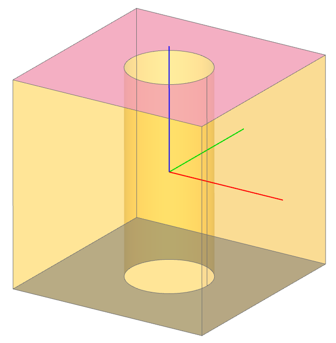
Here the two faces with “inner_wires” (i.e. holes) have been selected independent of orientation.