Objects
Objects are Python classes that take parameters as inputs and create 1D, 2D or 3D Shapes.
For example, a Torus is defined by a major and minor radii. In
Builder mode, objects are positioned with Locations while in Algebra mode, objects
are positioned with the * operator and shown in these examples:
with BuildPart() as disk:
    with BuildSketch():
        Circle(a)
        with Locations((b, 0.0)):
            Rectangle(c, c, mode=Mode.SUBTRACT)
        with Locations((0, b)):
            Circle(d, mode=Mode.SUBTRACT)
    extrude(amount=c)
sketch = Circle(a) - Pos(b, 0.0) * Rectangle(c, c) - Pos(0.0, b) * Circle(d)
disk = extrude(sketch, c)
The following sections describe the 1D, 2D and 3D objects:
Align
2D/Sketch and 3D/Part objects can be aligned relative to themselves, either centered, or justified right or left of each Axis. The following diagram shows how this alignment works in 2D:
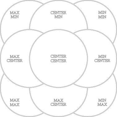
For example:
with BuildSketch():
    Circle(1, align=(Align.MIN, Align.MIN))
creates a circle who’s minimal X and Y values are on the X and Y axis and is located in the top right corner.
The Align enum has values: MIN, CENTER and MAX.
In 3D the align parameter also contains a Z align value but otherwise works in the same way.
Note that the align will also accept a single Align value which will be used on all axes -
as shown here:
with BuildSketch():
    Circle(1, align=Align.MIN)
Mode
With the Builder API the mode parameter controls how objects are combined with lines, sketches, or parts
under construction. The Mode enum has values:
ADD: fuse this object to the object under constructionSUBTRACT: cut this object from the object under constructionINTERSECT: intersect this object with the object under constructionREPLACE: replace the object under construction with this objectPRIVATE: don’t interact with the object under construction at all
The Algebra API doesn’t use the mode parameter - users combine objects with operators.
1D Objects
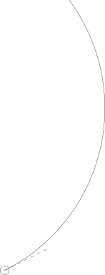
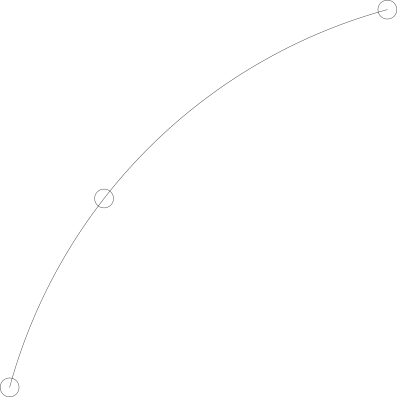
The following objects all can be used in BuildLine contexts. In Builder mode,
active Locations place 1D objects when they are added to the active builder.

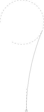
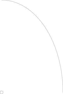
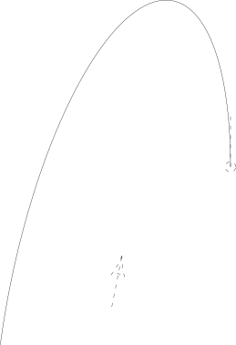
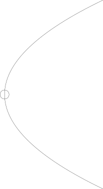
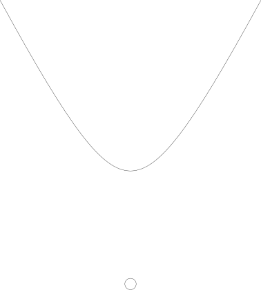
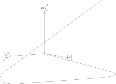
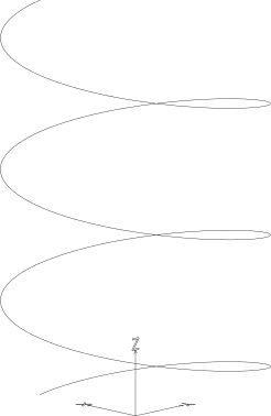
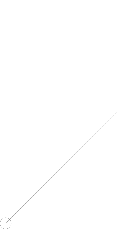
Reference
- class Airfoil(*args, **kwargs)[source]
Create an airfoil described by a 4-digit (or fractional) NACA airfoil (e.g. ‘2412’ or ‘2213.323’).
The NACA four-digit wing sections define the airfoil_code by: - First digit describing maximum camber as percentage of the chord. - Second digit describing the distance of maximum camber from the airfoil leading edge in tenths of the chord. - Last two digits describing maximum thickness of the airfoil as percent of the chord.
- Parameters:
airfoil_code – str The NACA 4-digit (or fractional) airfoil code (e.g. ‘2213.323’).
n_points – int Number of points per upper/lower surface.
finite_te – bool If True, enforces a finite trailing edge (default False).
mode (Mode, optional) – combination mode. Defaults to Mode.ADD
- property camber_line: Edge
Camber line of the airfoil as an Edge.
- camber_pos: float
Chordwise position of max camber (0–1)
- code: str
NACA code string (e.g. “2412”)
- finite_te: bool
If True, trailing edge is finite
- max_camber: float
Maximum camber as fraction of chord
- static parse_naca4(value: str | float) tuple[float, float, float][source]
Parse NACA 4-digit (or fractional) airfoil code into parameters.
- thickness: float
Maximum thickness as fraction of chord
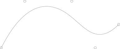
- class Bezier(*args, **kwargs)[source]
Line Object: Bezier Curve
Create a non-rational bezier curve defined by a sequence of points and include optional weights to create a rational bezier curve. The number of weights must match the number of control points.
- Parameters:
cntl_pnts (sequence[VectorLike]) – points defining the curve
weights (list[float], optional) – control point weights. Defaults to None
mode (Mode, optional) – combination mode. Defaults to Mode.ADD
- class BlendCurve(*args, **kwargs)[source]
Line Object: BlendCurve
Create a smooth Bézier-based transition curve between two existing edges.
The blend is constructed as a cubic (C1) or quintic (C2) Bézier curve whose control points are determined from the position, first derivative, and (for C2) second derivative of the input curves at the chosen endpoints. Optional scalar multipliers can be applied to the endpoint tangents to control the “tension” of the blend.
- Parameters:
curve0 (Edge) – First curve to blend from.
curve1 (Edge) – Second curve to blend to.
continuity (ContinuityLevel, optional) – Desired geometric continuity at the join: - ContinuityLevel.C0: position match only (straight line) - ContinuityLevel.C1: match position and tangent direction (cubic Bézier) - ContinuityLevel.C2: match position, tangent, and curvature (quintic Bézier) Defaults to ContinuityLevel.C2.
end_points (tuple[VectorLike, VectorLike] | None, optional) – Pair of points specifying the connection points on curve0 and curve1. Each must coincide (within TOLERANCE) with the start or end of the respective curve. If None, the closest pair of endpoints is chosen. Defaults to None.
tangent_scalars (tuple[float, float] | None, optional) – Scalar multipliers applied to the first derivatives at the start of curve0 and the end of curve1 before computing control points. Useful for adjusting the pull/tension of the blend without altering the base curves. Defaults to (1.0, 1.0).
mode (Mode, optional) – Boolean operation mode when used in a BuildLine context. Defaults to Mode.ADD.
- Raises:
ValueError – tangent_scalars must be a pair of float values.
ValueError – If specified end_points are not coincident with the start or end of their respective curves.
Example
>>> blend = BlendCurve(curve_a, curve_b, ContinuityLevel.C1, tangent_scalars=(1.2, 0.8))
>>> show(blend)
- class BSpline(*args, **kwargs)[source]
Line Object: BSpline
An exact B-spline edge defined directly from control points and knot data.
BSpline creates an exact B-spline from control points, a knot sequence, and optional weights. Control points define the control polygon that pulls the curve, but the curve does not generally pass through them. Knots define the parameter-space structure of the spline: they determine where polynomial spans begin and end and how smoothly those spans join. Repeated knot values indicate knot multiplicity. For a spline of degree p, a knot with multiplicity m has continuity C^(p-m) at that location, so increasing multiplicity reduces smoothness. Repeating the first and last knots degree + 1 times creates a clamped spline that starts and ends at the first and last control points. Optional weights create a rational B-spline, allowing some control points to pull more strongly than others and enabling exact representation of conic sections.`
Unlike
Spline, which creates an interpolated curve through a set of points usingGeomAPI_Interpolate,BSplinepreserves the supplied spline definition by building the underlying OCCTGeom_BSplineCurvefrom its poles, knot vector, optional weights, degree, and periodic flag.- Parameters:
control_points (Iterable[VectorLike]) – Control points (poles) defining the spline shape. These are not generally points on the curve.
knots (Iterable[float]) – Knot sequence for the spline. Repeated knot values are allowed and are converted internally into unique knot values plus multiplicities as required by OCCT.
degree (int) – Polynomial degree of the spline.
weights (Iterable[float] | None, optional) – Optional per-control-point weights for rational B-splines. If omitted, the spline is non-rational.
periodic (bool, optional) – Whether to create a periodic spline. Defaults to
False.mode (Mode, optional) – Builder combination mode. Defaults to
Mode.ADD.
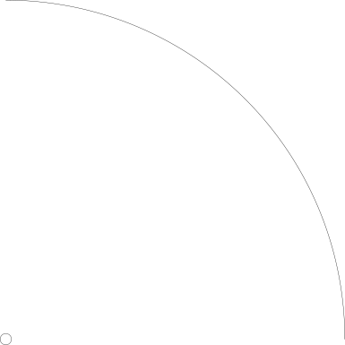
- class CenterArc(*args, **kwargs)[source]
Line Object: Center Arc
Create a circular arc defined by a center point and radius.
- Parameters:
center (VectorLike) – center point of arc
radius (float) – arc radius
start_angle (float) – arc starting angle from x-axis
arc_size (float | Shape | Axis | Location | Plane | VectorLike) –
angular size of arc or an arc limit.
When a limit object is provided instead of a numeric angular size, CenterArc constructs the valid arc(s) from the given start point, trims them at their first intersection with the limit, and returns the one requiring the shortest travel from the start. Therefore, one can only generate arcs < 180° using a limit. If neither valid arc intersects the limit, a ValueError is raised.
mode (Mode, optional) – combination mode. Defaults to Mode.ADD
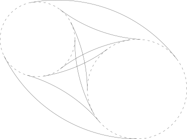
- class ConstrainedArcs(*args, **kwargs)[source]
Line Object: Arc(s) constrained by other geometric objects.
The result is always a Curve containing one or more Edges. If you need to access Edge-specific properties or methods (such as
arc_center), extract the edge or edges first:result = ConstrainedArcs(...) arc = result.edge() # extract the Edge center = arc.arc_center # now Edge methods are available
Note that in Builder mode the
selectorparameter must be provided or all results will be combined into the BuildLine context. In Algebra mode the selector can be applied as a parameter or in the normal way to the ConstrainedArcs object. The content of the selector is the same in both cases.Examples
An arc built from three edge constraints.
Algebra:
l4 = PolarLine((0, 0), 4, 60)
l5 = PolarLine((0, 0), 4, 40)
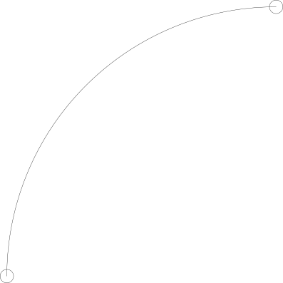
a3 = CenterArc((0, 0), 4, 0, 90)
ex_a3 = (
    ConstrainedArcs(l4, l5, a3, sagitta=Sagitta.BOTH).edges().sort_by(Edge.length)[0]
)
Builder:
with BuildLine() as arc_ex3:
    l4 = PolarLine((0, 0), 4, 60)
    l5 = PolarLine((0, 0), 4, 40)
    a3 = CenterArc((0, 0), 4, 0, 90)
    ex_a3 = ConstrainedArcs(
        l4,
        l5,
        a3,
        sagitta=Sagitta.BOTH,
        selector=lambda arcs: arcs.sort_by(Edge.length)[0],
    )
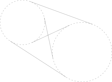
- class ConstrainedLines(*args, **kwargs)[source]
Line Object: Lines(s) constrained by other geometric objects.
The result is always a Curve containing one or more Edges. If you need to access Edge-specific properties or methods (such as
length), extract the edge or edges first:result = ConstrainedLines(...) lines = result.edges() # extract the Edges length = lines[1].length # now Edge methods are available
Note that in Builder mode the
selectorparameter must be provided or all results will be combined into the BuildLine context. In Algebra mode the selector can be applied as a parameter or in the normal way to the ConstrainedArcs object. The content of the selector is the same in both cases.
- class DoubleTangentArc(*args, **kwargs)[source]
Line Object: Double Tangent Arc
Create a circular arc defined by a point/tangent pair and another line find a tangent to.
The arc specified with TOP or BOTTOM depends on the geometry and isn’t predictable.
Contains a solver.
- Parameters:
- Raises:
RunTimeError – no double tangent arcs found
- class EllipticalCenterArc(*args, **kwargs)[source]
Line Object: Elliptical Center Arc
Create an elliptical arc defined by a center point, x- and y- radii.
- Parameters:
center (VectorLike) – ellipse center
x_radius (float) – x radius of the ellipse (along the x-axis of plane)
y_radius (float) – y radius of the ellipse (along the y-axis of plane)
start_angle (float, optional) – arc start angle from x-axis. Defaults to 0.0
arc_size (float | Shape | Axis | Location | Plane | VectorLike) –
angular size of arc (negative to change direction) or an arc limit.
When a limit object is provided instead of a numeric angular size, EllipticalCenterArc constructs the valid arc(s) from the given start point, trims them at their first intersection with the limit, and returns the one requiring the shortest travel from the start. Therefore, one can only generate arcs < 180° using a limit. If neither valid arc intersects the limit, a ValueError is raised.
rotation (float, optional) – angle to rotate arc. Defaults to 0.0
mode (Mode, optional) – combination mode. Defaults to Mode.ADD
- class EllipticalStartArc(*args, **kwargs)[source]
Line Object: EllipticalStartArc
Create a circular arc defined by a start point/tangent pair, radius and arc size.
- Parameters:
start_pnt (VectorLike) – start point
start_tangent (VectorLike) – tangent at start point
x_radius (float) – x radius of the ellipse (along the x-axis of plane)
y_radius (float) – y radius of the ellipse (along the y-axis of plane)
arc_size (float) – angular size of arc (negative to change direction)
start_angle (float) – angular position of the start point
major_axis_dir (VectorLike) – direction of ellipse x-axis
mode (Mode, optional) – combination mode. Defaults to Mode.ADD
Note
One of start_angle or major_axis_dir must be provided.
- class ParabolicCenterArc(*args, **kwargs)[source]
Line Object: Parabolic Center Arc
Create a parabolic arc defined by a vertex point and focal length (distance from focus to vertex).
- Parameters:
vertex (VectorLike) – parabola vertex
focal_length (float) – focal length the parabola (distance from the vertex to focus along the x-axis of plane)
start_angle (float, optional) – arc start angle. Defaults to 0.0
arc_size (float | Shape | Axis | Location | Plane | VectorLike) –
angular size of arc (negative to change direction) or an arc limit.
When a limit object is provided instead of a numeric angular size, ParabolicCenterArc constructs candidate arcs from the given start point, trims them at their first intersection with the limit, and returns the one requiring the shortest travel from the start. If neither valid arc intersects the limit, a ValueError is raised.
rotation (float, optional) – angle to rotate arc. Defaults to 0.0
mode (Mode, optional) – combination mode. Defaults to Mode.ADD
- class HyperbolicCenterArc(*args, **kwargs)[source]
Line Object: Hyperbolic Center Arc
Create a hyperbolic arc defined by a center point and focal length (distance from focus to vertex).
- Parameters:
center (VectorLike) – hyperbola center
x_radius (float) – x radius of the ellipse (along the x-axis of plane)
y_radius (float) – y radius of the ellipse (along the y-axis of plane)
start_angle (float, optional) – arc start angle from x-axis. Defaults to 0.0
arc_size (float | Shape | Axis | Location | Plane | VectorLike) –
angular size of arc (negative to change direction) or an arc limit.
When a limit object is provided instead of a numeric angular size, HyperbolicCenterArc constructs candidate arcs from the given start point, trims them at their first intersection with the limit, and returns the one requiring the shortest travel from the start. If neither valid arc intersects the limit, a ValueError is raised.
rotation (float, optional) – angle to rotate arc. Defaults to 0.0
mode (Mode, optional) – combination mode. Defaults to Mode.ADD
- class FilletPolyline(*args, **kwargs)[source]
Line Object: Fillet Polyline Create a sequence of straight lines defined by successive points that are filleted to a given radius.
- Parameters:
pts (VectorLike | Iterable[VectorLike]) – sequence of two or more points
radius (float | Iterable[float]) – radius to fillet at each vertex or a single value for all vertices. A radius of 0 will create a sharp corner (vertex without fillet).
close (bool, optional) – close end points with extra Edge and corner fillets. Defaults to False
mode (Mode, optional) – combination mode. Defaults to Mode.ADD
- Raises:
ValueError – Two or more points not provided
ValueError – radius must be non-negative
- class Helix(*args, **kwargs)[source]
Line Object: Helix
Create a helix defined by pitch, height, and radius. The helix may have a taper defined by cone_angle.
If cone_angle is not 0, radius is the initial helix radius at center. cone_angle > 0 increases the final radius. cone_angle < 0 decreases the final radius.
- Parameters:
pitch (float) – distance between loops
height (float) – helix height
radius (float) – helix radius
center (VectorLike, optional) – center point. Defaults to (0, 0, 0)
direction (VectorLike, optional) – direction of central axis. Defaults to (0, 0, 1)
cone_angle (float, optional) – conical angle from direction. Defaults to 0
lefthand (bool, optional) – left handed helix. Defaults to False
mode (Mode, optional) – combination mode. Defaults to Mode.ADD
- class IntersectingLine(*args, **kwargs)[source]
Intersecting Line Object: Line
Create a straight line defined by a point/direction pair and another line to intersect.
- class JernArc(*args, **kwargs)[source]
Line Object: Jern Arc
Create a circular arc defined by a start point/tangent pair, radius and arc size or arc limit.
- Parameters:
start (VectorLike) – start point
tangent (VectorLike) – tangent at start point
radius (float) – arc radius
arc_size (float | Shape | Axis | Location | Plane | VectorLike) –
angular size of arc (negative to change direction) or an arc limit.
When a limit object is provided instead of a numeric angular size, JernArc constructs the valid tangent arc(s) from the given start point and tangent, trims them at their first intersection with the limit, and returns the one requiring the shortest travel from the start. If neither valid arc intersects the limit, a ValueError is raised.
mode (Mode, optional) – combination mode. Defaults to Mode.ADD
- Variables:
- class Line(*args, **kwargs)[source]
Line Object: Line
Create a straight line defined by two points.
- Parameters:
pts (VectorLike | Iterable[VectorLike]) – sequence of two points
mode (Mode, optional) – combination mode. Defaults to Mode.ADD
- Raises:
ValueError – Two point not provided
- class PolarLine(*args, **kwargs)[source]
Line Object: Polar Line
Create a straight line defined by a start point, length, and angle. The length can specify the DIAGONAL, HORIZONTAL, or VERTICAL component of the triangle defined by the angle.
Alternatively, the length parameter can contain a limit to the length of the line in the form of another object. If the PolarLine doesn’t contact the limit an error will be generated.
Example
p = PolarLine(start=(2, 0), length=Axis.Y, angle=135)
- Parameters:
start (VectorLike) – start point
length (float | Shape | Axis | Location | Plane | VectorLike) – line length (float) or limit limit
angle (float, optional) – angle from the local x-axis
direction (VectorLike, optional) – vector direction to determine angle
length_mode (LengthMode, optional) – how length defines the line. Defaults to LengthMode.DIAGONAL
mode (Mode, optional) – combination mode. Defaults to Mode.ADD
- Raises:
ValueError – Either angle or direction must be provided
ValueError – Polar line doesn’t intersect length limit
- class Polyline(*args, **kwargs)[source]
Line Object: Polyline
Create a sequence of straight lines defined by successive points.
- Parameters:
pts (VectorLike | Iterable[VectorLike]) – sequence of two or more points
close (bool, optional) – close by generating an extra Edge. Defaults to False
mode (Mode, optional) – combination mode. Defaults to Mode.ADD
- Raises:
ValueError – Two or more points not provided
- class RadiusArc(*args, **kwargs)[source]
Line Object: Radius Arc
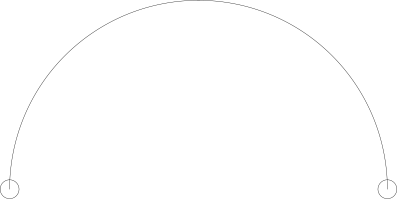
Create a circular arc defined by two points and a radius.
- Parameters:
start_point (VectorLike) – start point
end_point (VectorLike) – end point
radius (float) – arc radius
short_sagitta (bool) – If True selects the short sagitta (height of arc from chord), else the long sagitta crossing the center. Defaults to True
mode (Mode, optional) – combination mode. Defaults to Mode.ADD
- Raises:
ValueError – Insufficient radius to connect end points
- class SagittaArc(*args, **kwargs)[source]
Line Object: Sagitta Arc
Create a circular arc defined by two points and the sagitta (height of the arc from chord).
- Parameters:
start_point (VectorLike) – start point
end_point (VectorLike) – end point
sagitta (float) – arc height from chord between points
mode (Mode, optional) – combination mode. Defaults to Mode.ADD
- class Spline(*args, **kwargs)[source]
Line Object: Spline
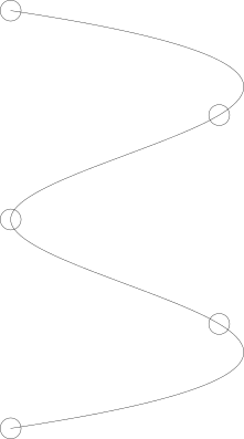
Create a spline defined by a sequence of points, optionally constrained by tangents. Tangents and tangent scalars must have length of 2 for only the end points or a length of the number of points.
- Parameters:
pts (VectorLike | Iterable[VectorLike]) – sequence of two or more points
tangents (Iterable[VectorLike], optional) – tangent directions. Defaults to None
tangent_scalars (Iterable[float], optional) – tangent scales. Defaults to None
periodic (bool, optional) – make the spline periodic (closed). Defaults to False
mode (Mode, optional) – combination mode. Defaults to Mode.ADD
- class TangentArc(*args, **kwargs)[source]
Line Object: Tangent Arc
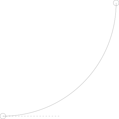
Create a circular arc defined by two points and a tangent.
- Parameters:
pts (VectorLike | Iterable[VectorLike]) – sequence of two points
tangent (VectorLike) – tangent to constrain arc
tangent_from_first (bool, optional) – apply tangent to first point. Applying tangent to end point will flip the orientation of the arc. Defaults to True
mode (Mode, optional) – combination mode. Defaults to Mode.ADD
- Raises:
ValueError – Two points are required
- class ThreePointArc(*args, **kwargs)[source]
Line Object: Three Point Arc
Create a circular arc defined by three points.
- Parameters:
pts (VectorLike | Iterable[VectorLike]) – sequence of three points
mode (Mode, optional) – combination mode. Defaults to Mode.ADD
- Raises:
ValueError – Three points must be provided
2D Objects



Reference
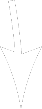
- class Arrow(*args, **kwargs)[source]
Sketch Object: Arrow with shaft
- Parameters:
arrow_size (float) – arrow head tip to tail length
shaft_width (float) – line width of shaft
head_at_start (bool, optional) – Defaults to True.
head_type (HeadType, optional) – arrow head shape. Defaults to HeadType.CURVED.
mode (Mode, optional) – _description_. Defaults to Mode.ADD.
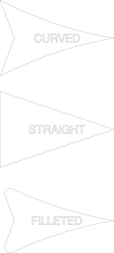
- class ArrowHead(*args, **kwargs)[source]
Sketch Object: ArrowHead
- Parameters:
size (float) – tip to tail length
head_type (HeadType, optional) – arrow head shape. Defaults to HeadType.CURVED.
rotation (float, optional) – rotation in degrees. Defaults to 0.
mode (Mode, optional) – combination mode. Defaults to Mode.ADD.
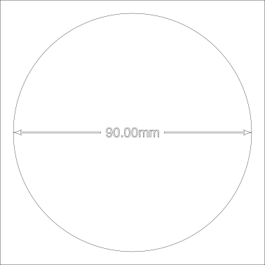
- class Circle(*args, **kwargs)[source]
Sketch Object: Circle
Create a circle defined by radius.
- Parameters:
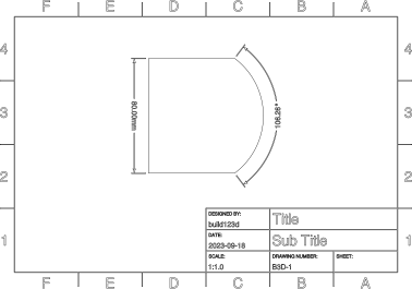
- class DimensionLine(*args, **kwargs)[source]
Sketch Object: DimensionLine
Create a dimension line typically for internal measurements. Typically used for (but not restricted to) inside dimensions, a dimension line often as arrows on either side of a dimension or label.
There are three options depending on the size of the text and length of the dimension line: Type 1) The label and arrows fit within the length of the path Type 2) The text fit within the path and the arrows go outside Type 3) Neither the text nor the arrows fit within the path
- Parameters:
path (PathDescriptor) – a very general type of input used to describe the path the dimension line will follow.
draft (Draft) – instance of Draft dataclass
sketch (Sketch) – the Sketch being created to check for possible overlaps. In builder mode the active Sketch will be used if None is provided.
label (str, optional) – a text string which will replace the length (or arc length) that would otherwise be extracted from the provided path. Providing a label is useful when illustrating a parameterized input where the name of an argument is desired not an actual measurement. Defaults to None.
arrows (tuple[bool, bool], optional) – a pair of boolean values controlling the placement of the start and end arrows. Defaults to (True, True).
tolerance (float | tuple[float, float], optional) – an optional tolerance value to add to the extracted length value. If a single tolerance value is provided it is shown as ± the provided value while a pair of values are shown as separate + and - values. Defaults to None.
label_angle (bool, optional) – a flag indicating that instead of an extracted length value, the size of the circular arc extracted from the path should be displayed in degrees.
mode (Mode, optional) – combination mode. Defaults to Mode.ADD.
- Raises:
ValueError – Only 2 points allowed for dimension lines
ValueError – No output - no arrows selected
- dimension
length of the dimension
- class Draft(font_size: float = 5.0, font: str = 'Arial', font_style: ~build123d.build_enums.FontStyle = <FontStyle.REGULAR>, head_type: ~build123d.build_enums.HeadType = <HeadType.CURVED>, arrow_length: float = 3.0, line_width: float = 0.5, pad_around_text: float = 2.0, unit: ~build123d.build_enums.Unit = <Unit.MM>, number_display: ~build123d.build_enums.NumberDisplay = <NumberDisplay.DECIMAL>, display_units: bool = True, decimal_precision: int = 2, fractional_precision: int = 64, extension_gap: float = 2.0)[source]
Documenting build123d designs with dimension and extension lines as well as callouts.
- Parameters:
font_size (float) – size of the text in dimension lines and callouts. Defaults to 5.0.
font (str) – font to use for text. Defaults to “Arial”.
font_style – text style. Defaults to FontStyle.REGULAR.
head_type (HeadType, optional) – arrow head shape. Defaults to HeadType.CURVED.
arrow_length (float) – arrow head length. Defaults to 3.0.
line_width (float) – thickness of all lines. Defaults to 0.5.
pad_around_text (float) – amount of padding around text. Defaults to 2.0.
unit (Unit) – measurement unit. Defaults to Unit.MM.
number_display (NumberDisplay) – numbers as decimal or fractions. Default to NumberDisplay.DECIMAL.
display_units (bool) – control the display of units with numbers. Defaults to True.
decimal_precision (int) – number of decimal places when displaying numbers. Defaults to 2.
fractional_precision (int) – maximum fraction denominator - must be a factor of 2. Defaults to 64.
extension_gap (float) – gap between the point and start of extension line in extension_line. Defaults to 2.0.
- arrow_length: float = 3.0
- decimal_precision: int = 2
- display_units: bool = True
- extension_gap: float = 2.0
- font: str = 'Arial'
- font_size: float = 5.0
- font_style: FontStyle = 1
- fractional_precision: int = 64
- head_type: HeadType = 2
- property is_metric: bool
Are metric units being used
- line_width: float = 0.5
- number_display: NumberDisplay = 1
- pad_around_text: float = 2.0
- unit: Unit = 'mm'
- unit_LUT: ClassVar[dict] = {False: '"', True: 'mm'}
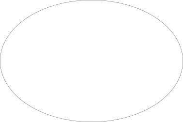
- class Ellipse(*args, **kwargs)[source]
Sketch Object: Ellipse
Create an ellipse defined by x- and y- radii.
- Parameters:
x_radius (float) – x radius of the ellipse (along the x-axis of plane)
y_radius (float) – y radius of the ellipse (along the y-axis of plane)
rotation (float, optional) – angle to rotate object. Defaults to 0
align (Align | tuple[Align, Align], optional) – align MIN, CENTER, or MAX of object. Defaults to (Align.CENTER, Align.CENTER)
mode (Mode, optional) – combination mode. Defaults to Mode.ADD
- class ExtensionLine(*args, **kwargs)[source]
Sketch Object: Extension Line
Create a dimension line with two lines extending outward from the part to dimension. Typically used for (but not restricted to) outside dimensions, with a pair of lines extending from the edge of a part to a dimension line.
- Parameters:
border (PathDescriptor) – a very general type of input defining the object to be dimensioned. Typically this value would be extracted from the part but is not restricted to this use.
offset (float | VectorLike) – displacement of the dimension line from the edge of the object. A
floatis a signed perpendicular distance (the legacy behaviour, where the sign selects the side). AVectorLikeis an explicit displacement in the drawing (XY) plane: its magnitude is the distance, its direction selects the side, removing the sign-convention guesswork. The vector must be perpendicular to the dimension line (a small tolerance is allowed); ifmeasurement_directionis also given the two must be perpendicular, otherwise the dimension line direction is inferred perpendicular to the offset.draft (Draft) – instance of Draft dataclass
label (str, optional) – a text string which will replace the length (or arc length) that would otherwise be extracted from the provided path. Providing a label is useful when illustrating a parameterized input where the name of an argument is desired not an actual measurement. Defaults to None.
arrows (tuple[bool, bool], optional) – a pair of boolean values controlling the placement of the start and end arrows. Defaults to (True, True).
tolerance (float | tuple[float, float], optional) – an optional tolerance value to add to the extracted length value. If a single tolerance value is provided it is shown as ± the provided value while a pair of values are shown as separate + and - values. Defaults to None.
label_angle (bool, optional) – a flag indicating that instead of an extracted length value, the size of the circular arc extracted from the path should be displayed in degrees. Defaults to False.
measurement_direction (VectorLike, optional) – Vector line which to project the dimension against. Offset start point is the position of the start of border. Defaults to None.
mode (Mode, optional) – combination mode. Defaults to Mode.ADD.
- dimension
length of the dimension
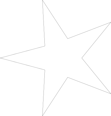
- class Polygon(*args, **kwargs)[source]
Sketch Object: Polygon
Create a polygon defined by given sequence of points.
Note: the order of the points defines the resulting normal of the Face in Algebra mode, where counter-clockwise order creates an upward normal while clockwise order a downward normal. In Builder mode, the Face is added with an upward normal.
- Parameters:
pts (VectorLike | Iterable[VectorLike]) – sequence of points defining the vertices of the polygon
rotation (float, optional) – angle to rotate object. Defaults to 0
align (Align | tuple[Align, Align], optional) – align MIN, CENTER, or MAX of object. Defaults to (Align.NONE, Align.NONE)
mode (Mode, optional) – combination mode. Defaults to Mode.ADD
- class Rectangle(*args, **kwargs)[source]
Sketch Object: Rectangle
Create a rectangle defined by width and height.
- Parameters:
width (float) – rectangle width
height (float) – rectangle height
rotation (float, optional) – angle to rotate object. Defaults to 0
align (Align | tuple[Align, Align], optional) – align MIN, CENTER, or MAX of object. Defaults to (Align.CENTER, Align.CENTER)
mode (Mode, optional) – combination mode. Defaults to Mode.ADD
- class RectangleRounded(*args, **kwargs)[source]
Sketch Object: Rectangle Rounded
Create a rectangle defined by width and height with filleted corners.
- Parameters:
width (float) – rectangle width
height (float) – rectangle height
radius (float) – fillet radius
rotation (float, optional) – angle to rotate object. Defaults to 0
align (Align | tuple[Align, Align], optional) – align MIN, CENTER, or MAX of object. Defaults to (Align.CENTER, Align.CENTER)
mode (Mode, optional) – combination mode. Defaults to Mode.ADD
- class RegularPolygon(*args, **kwargs)[source]
Sketch Object: Regular Polygon
Create a regular polygon defined by radius and side count. Use major_radius to define whether the polygon circumscribes (along the vertices) or inscribes (along the sides) the radius circle.
- Parameters:
radius (float) – construction radius
side_count (int) – number of sides
major_radius (bool) – If True the radius is the major radius (circumscribed circle), else the radius is the minor radius (inscribed circle). Defaults to True
rotation (float, optional) – angle to rotate object. Defaults to 0
align (Align | tuple[Align, Align], optional) – align MIN, CENTER, or MAX of object. Defaults to (Align.CENTER, Align.CENTER)
mode (Mode, optional) – combination mode. Defaults to Mode.ADD
- apothem: float
radius of the inscribed circle or minor radius
- radius: float
radius of the circumscribed circle or major radius
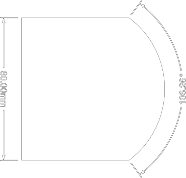
- class SlotArc(*args, **kwargs)[source]
Sketch Object: Slot Arc
Create a slot defined by a line and height. May be an arc, stright line, spline, etc.
- class SlotCenterPoint(*args, **kwargs)[source]
Sketch Object: Slot Center Point
Create a slot defined by the center of the slot and the center of one end arc. The slot will be symmetric about the center point.
- Parameters:
center (VectorLike) – center point
point (VectorLike) – center of arc point
height (float) – diameter of end arcs
rotation (float, optional) – angle to rotate object. Defaults to 0
mode (Mode, optional) – combination mode. Defaults to Mode.ADD
- class SlotCenterToCenter(*args, **kwargs)[source]
Sketch Object: Slot Center To Center
Create a slot defined by the distance between the centers of the two end arcs.
- Parameters:
center_separation (float) – distance between arc centers
height (float) – diameter of end arcs
rotation (float, optional) – angle to rotate object. Defaults to 0
mode (Mode, optional) – combination mode. Defaults to Mode.ADD
- class SlotOverall(*args, **kwargs)[source]
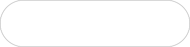
Sketch Object: Slot Overall
Create a slot defined by the overall width and height.
- Parameters:
width (float) – overall width of slot
height (float) – diameter of end arcs
rotation (float, optional) – angle to rotate object. Defaults to 0
align (Align | tuple[Align, Align], optional) – align MIN, CENTER, or MAX of object. Defaults to (Align.CENTER, Align.CENTER)
mode (Mode, optional) – combination mode. Defaults to Mode.ADD
- class Superellipse(*args, **kwargs)[source]
Sketch Object: Superellipse
Create an superellipse (“squircle”) defined by width, height, and order.
- Parameters:
width (float) – superellipse width
height (float) – superellipse height
order (float, optional) – order of the superellipse. Defaults to 4
point_count (int, optional) – number of points per quadrant to use for generating the superellipse. Ignored when order == 1 or 2. Defaults to 16
rotation (float, optional) – angle to rotate object. Defaults to 0
align (Align | tuple[Align, Align], optional) – align MIN, CENTER, or MAX of object. Defaults to (Align.CENTER, Align.CENTER)
mode (Mode, optional) – combination mode. Defaults to Mode.ADD
- class TechnicalDrawing(*args, **kwargs)[source]
Sketch Object: TechnicalDrawing
The border of a technical drawing with external frame and text box.
- Parameters:
designed_by (str, optional) – Defaults to “build123d”.
design_date (date, optional) – Defaults to date.today().
page_size (PageSize, optional) – Defaults to PageSize.A4.
title (str, optional) – drawing title. Defaults to “Title”.
sub_title (str, optional) – drawing sub title. Defaults to “Sub Title”.
drawing_number (str, optional) – Defaults to “B3D-1”.
sheet_number (int, optional) – Defaults to None.
drawing_scale (float, optional) – displays as 1:value. Defaults to 1.0.
nominal_text_size (float, optional) – size of title text. Defaults to 10.0.
line_width (float, optional) – Defaults to 0.5.
mode (Mode, optional) – combination mode. Defaults to Mode.ADD.
- margin = 5
- page_sizes = {<PageSize.A0>: (1189, 841), <PageSize.A10>: (37, 26), <PageSize.A1>: (841, 594), <PageSize.A2>: (594, 420), <PageSize.A3>: (420, 297), <PageSize.A4>: (297, 210), <PageSize.A5>: (210, 148.5), <PageSize.A6>: (148.5, 105), <PageSize.A7>: (105, 74), <PageSize.A8>: (74, 52), <PageSize.A9>: (52, 37), <PageSize.LEDGER>: (431.79999999999995, 279.4), <PageSize.LEGAL>: (355.59999999999997, 215.89999999999998), <PageSize.LETTER>: (279.4, 215.89999999999998)}
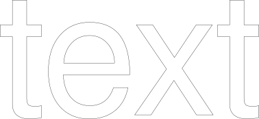
- class Text(*args, **kwargs)[source]
Sketch Object: Text
Create text defined by text string and font size.
Fonts installed to the system can be specified by name and FontStyle. Fonts with subfamilies not in FontStyle should be specified with the subfamily name, e.g. “Arial Black”. Alternatively, a specific font file can be specified with font_path.
Use available_fonts() to list available font names for font and FontStyles. Note: on Windows, fonts must be installed with “Install for all users” to be found by name.
Not all fonts have every FontStyle available, however ITALIC and BOLDITALIC will still italicize the font if the respective font file is not available.
text_align specifies alignment of text inside the bounding box, while align the aligns the bounding box itself.
Optionally, the Text can be positioned on a non-linear edge or wire with a path and position_on_path.
- Parameters:
txt (str) – text to render
font_size (float) – size of the font in model units
font (str, optional) – requested font name. After construction, this attribute contains the resolved font name. Defaults to “Arial”
font_path (PathLike | str, optional) – system path to font file. After construction, this attribute contains the resolved font path. Defaults to None
font_style (Font_Style, optional) – font style, REGULAR, BOLD, BOLDITALIC, or ITALIC. Defaults to Font_Style.REGULAR
text_align (tuple[TextAlign, TextAlign], optional) – horizontal text align LEFT, CENTER, or RIGHT. Vertical text align BOTTOM, CENTER, TOP, or TOPFIRSTLINE. Defaults to (TextAlign.CENTER, TextAlign.CENTER)
align (Align | tuple[Align, Align], optional) – align MIN, CENTER, or MAX of object. Defaults to None
path (Edge | Wire, optional) – path for text to follow. Defaults to None
position_on_path (float, optional) – the relative location on path to position the text, values must be between 0.0 and 1.0. Defaults to 0.0
single_line_width (float, optional) – width of outlined single line font. Defaults to 4% of font_size
rotation (float, optional) – angle to rotate object. Defaults to 0
mode (Mode, optional) – combination mode. Defaults to Mode.ADD
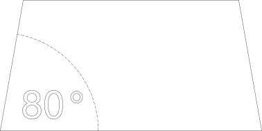
- class Trapezoid(*args, **kwargs)[source]
Sketch Object: Trapezoid
Create a trapezoid defined by major width, height, and interior angle(s).
- Parameters:
width (float) – trapezoid major width
height (float) – trapezoid height
left_side_angle (float) – bottom left interior angle
right_side_angle (float, optional) – bottom right interior angle. If not provided, the trapezoid will be symmetric. Defaults to None
rotation (float, optional) – angle to rotate object. Defaults to 0
align (Align | tuple[Align, Align], optional) – align MIN, CENTER, or MAX of object. Defaults to (Align.CENTER, Align.CENTER)
mode (Mode, optional) – combination mode. Defaults to Mode.ADD
- Raises:
ValueError – Give angles result in an invalid trapezoid
- class Triangle(*args, **kwargs)[source]
Sketch Object: Triangle
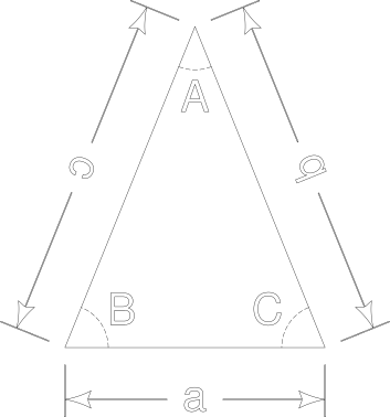
Create a triangle defined by one side length and any of two other side lengths or interior angles. The interior angles are opposite the side with the same designation (i.e. side ‘a’ is opposite angle ‘A’). Side ‘a’ is the bottom side, followed by ‘b’ on the right, going counter-clockwise.
- Parameters:
a (float, optional) – side ‘a’ length. Defaults to None
b (float, optional) – side ‘b’ length. Defaults to None
c (float, optional) – side ‘c’ length. Defaults to None
A (float, optional) – interior angle ‘A’. Defaults to None
B (float, optional) – interior angle ‘B’. Defaults to None
C (float, optional) – interior angle ‘C’. Defaults to None
rotation (float, optional) – angle to rotate object. Defaults to 0
align (Align | tuple[Align, Align], optional) – align MIN, CENTER, or MAX of object. Defaults to None
mode (Mode, optional) – combination mode. Defaults to Mode.ADD
- Raises:
ValueError – One length and two other values were not provided
- A
interior angle ‘A’ in degrees
- B
interior angle ‘B’ in degrees
- C
interior angle ‘C’ in degrees
- a
length of side ‘a’
- b
length of side ‘b’
- c
length of side ‘c’
- edge_a
edge ‘a’
- edge_b
edge ‘b’
- edge_c
edge ‘c’
- vertex_A
vertex ‘A’
- vertex_B
vertex ‘B’
- vertex_C
vertex ‘C’
3D Objects
Reference
- class BasePartObject(*args, **kwargs)[source]
Base class for all BuildPart objects & operations
- Parameters:
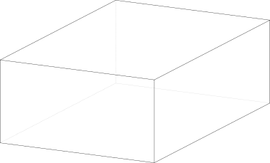
- class Box(*args, **kwargs)[source]
Part Object: Box
Create a box defined by length, width, and height.
- Parameters:
length (float) – box length
width (float) – box width
height (float) – box height
rotation (RotationLike, optional) – angles to rotate about axes. Defaults to (0, 0, 0)
align (Align | tuple[Align, Align, Align] | None, optional) – align MIN, CENTER, or MAX of object. Defaults to (Align.CENTER, Align.CENTER, Align.CENTER)
mode (Mode, optional) – combine mode. Defaults to Mode.ADD
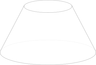
- class Cone(*args, **kwargs)[source]
Part Object: Cone
Create a cone defined by bottom radius, top radius, and height.
- Parameters:
bottom_radius (float) – bottom radius
top_radius (float) – top radius, may be zero
height (float) – cone height
arc_size (float, optional) – angular size of cone. Defaults to 360
rotation (RotationLike, optional) – angles to rotate about axes. Defaults to (0, 0, 0)
align (Align | tuple[Align, Align, Align] | None, optional) – align MIN, CENTER, or MAX of object. Defaults to (Align.CENTER, Align.CENTER, Align.CENTER)
mode (Mode, optional) – combine mode. Defaults to Mode.ADD
- class ConvexPolyhedron(*args, **kwargs)[source]
Part Object: ConvexPolyhedron
Create a convex solid from the convex hull of the provided points.
- Parameters:
points (Iterable[VectorLike]) – vertices of the polyhedron
rotation (RotationLike, optional) – angles to rotate about axes. Defaults to (0, 0, 0)
align (Align | tuple[Align, Align, Align] | None, optional) – align MIN, CENTER, or MAX of object. Defaults to Align.NONE
mode (Mode, optional) – combine mode. Defaults to Mode.ADD
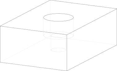
- class CounterBoreHole(*args, **kwargs)[source]
Part Operation: Counter Bore Hole
Create a counter bore hole defined by radius, counter bore radius, counter bore and depth.
- Parameters:
radius (float) – hole radius
counter_bore_radius (float) – counter bore radius
counter_bore_depth (float) – counter bore depth
depth (float, optional) – hole depth, through part if None. Defaults to None
mode (Mode, optional) – combination mode. Defaults to Mode.SUBTRACT
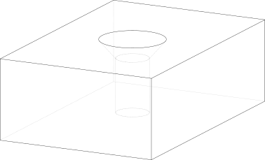
- class CounterSinkHole(*args, **kwargs)[source]
Part Operation: Counter Sink Hole
Create a countersink hole defined by radius, countersink radius, countersink angle, and depth.
- Parameters:
radius (float) – hole radius
counter_sink_radius (float) – countersink radius
depth (float, optional) – hole depth, through part if None. Defaults to None
counter_sink_angle (float, optional) – cone angle. Defaults to 82
mode (Mode, optional) – combination mode. Defaults to Mode.SUBTRACT
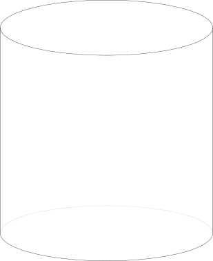
- class Cylinder(*args, **kwargs)[source]
Part Object: Cylinder
Create a cylinder defined by radius and height.
- Parameters:
radius (float) – cylinder radius
height (float) – cylinder height
arc_size (float, optional) – angular size of cone. Defaults to 360.
rotation (RotationLike, optional) – angles to rotate about axes. Defaults to (0, 0, 0)
align (Align | tuple[Align, Align, Align] | None, optional) – align MIN, CENTER, or MAX of object. Defaults to (Align.CENTER, Align.CENTER, Align.CENTER)
mode (Mode, optional) – combine mode. Defaults to Mode.ADD
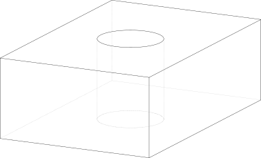
- class Hole(*args, **kwargs)[source]
Part Operation: Hole
Create a hole defined by radius and depth.
- Parameters:
radius (float) – hole radius
depth (float, optional) – hole depth, through part if None. Defaults to None
mode (Mode, optional) – combination mode. Defaults to Mode.SUBTRACT
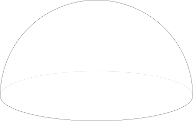
- class Sphere(*args, **kwargs)[source]
Part Object: Sphere
Create a sphere defined by a radius.
- Parameters:
radius (float) – sphere radius
arc_size1 (float, optional) – angular size of bottom hemisphere. Defaults to -90.
arc_size2 (float, optional) – angular size of top hemisphere. Defaults to 90.
arc_size3 (float, optional) – angular revolution about pole. Defaults to 360.
rotation (RotationLike, optional) – angles to rotate about axes. Defaults to (0, 0, 0)
align (Align | tuple[Align, Align, Align] | None, optional) – align MIN, CENTER, or MAX of object. Defaults to (Align.CENTER, Align.CENTER, Align.CENTER)
mode (Mode, optional) – combine mode. Defaults to Mode.ADD
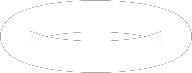
- class Torus(*args, **kwargs)[source]
Part Object: Torus
Create a torus defined by major and minor radii.
- Parameters:
major_radius (float) – major torus radius
minor_radius (float) – minor torus radius
minor_start_angle (float, optional) – angle to start minor arc. Defaults to 0
minor_end_angle (float, optional) – angle to end minor arc. Defaults to 360
major_angle (float, optional) – angle to revolve minor arc. Defaults to 360
rotation (RotationLike, optional) – angles to rotate about axes. Defaults to (0, 0, 0)
align (Align | tuple[Align, Align, Align] | None, optional) – align MIN, CENTER, or MAX of object. Defaults to (Align.CENTER, Align.CENTER, Align.CENTER)
mode (Mode, optional) – combine mode. Defaults to Mode.ADD
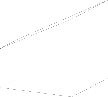
- class Wedge(*args, **kwargs)[source]
Part Object: Wedge
Create a wedge with a near face defined by xsize and z size, a far face defined by xmin to xmax and zmin to zmax, and a depth of ysize.
- Parameters:
xsize (float) – length of near face along x-axis
ysize (float) – length of part along y-axis
zsize (float) – length of near face z-axis
xmin (float) – minimum position far face along x-axis
zmin (float) – minimum position far face along z-axis
xmax (float) – maximum position far face along x-axis
zmax (float) – maximum position far face along z-axis
rotation (RotationLike, optional) – angles to rotate about axes. Defaults to (0, 0, 0)
align (Align | tuple[Align, Align, Align] | None, optional) – align MIN, CENTER, or MAX of object. Defaults to (Align.CENTER, Align.CENTER, Align.CENTER)
mode (Mode, optional) – combine mode. Defaults to Mode.ADD
Text
Create Text Object
Create text object or add to BuildSketch using Text:

text = "The quick brown fox jumped over the lazy dog."
Text(text, 10)
Specify font and style. Fonts have up to 4 font styles: REGULAR, BOLD,
ITALIC, BOLDITALIC. All fonts can use ITALIC even if only
REGULAR is defined.
Text(text, 10, "Arial", font_style=FontStyle.BOLD)
Find available fonts on system and available styles:
from pprint import pprint
pprint(available_fonts())
[
 ...
 Font(name='Arial', styles=('REGULAR', 'BOLD', 'BOLDITALIC', 'ITALIC')),
 Font(name='Arial Black', styles=('REGULAR',)),
 Font(name='Arial Narrow', styles=('REGULAR', 'BOLD', 'BOLDITALIC', 'ITALIC')),
 Font(name='Arial Rounded MT Bold', styles=('REGULAR',)),
 ...
]
Font faces like "Arial Black" or "Arial Narrow" must be specified
by name rather than FontStyle:
Text(text, 10, "Arial Black")
Specify a font file directly by filename:
Text(text, 10, font_path="DejaVuSans.ttf")
Fonts added via font_path persist in the font list:
Text(text, 10, font_path="SourceSans3-VariableFont_wght.ttf")
pprint([f.name for f in available_fonts() if "Source Sans" in f.name])
Text(text, 10, "Source Sans 3 Medium")
['Source Sans 3',
 'Source Sans 3 Black',
 'Source Sans 3 ExtraBold',
 'Source Sans 3 ExtraLight',
 ...]
Add a font file to FontManager if a font is reused in the script or
contains multiple font faces:
new_font_faces = FontManager().register_font("Roboto-VariableFont_wdth,wght.ttf")
pprint(new_font_faces)
Text(text, 10, "Roboto")
Text(text, 10, "Roboto Black")
['Roboto Thin',
 'Roboto ExtraLight',
 'Roboto Light',
 'Roboto',
  ...]
Placement
Multiline text has two methods of alignment.
text_align aligns the text relative to its Location:
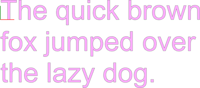
Text(text, 10, text_align=(TextAlign.LEFT, TextAlign.TOPFIRSTLINE))
align aligns the object bounding box relative to its Location after
text alignment:
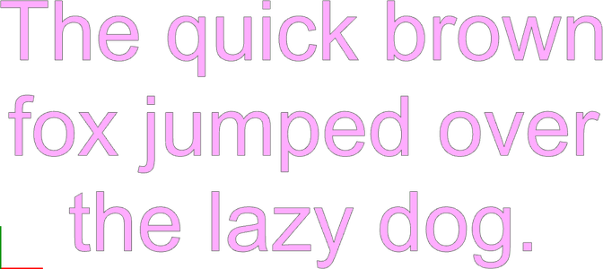
text = "The quick brown\nfox jumped over\nthe lazy dog."
Text(text, 10, align=(Align.MIN, Align.MIN))
Place text along an Edge or Wire with path and position_on_path:
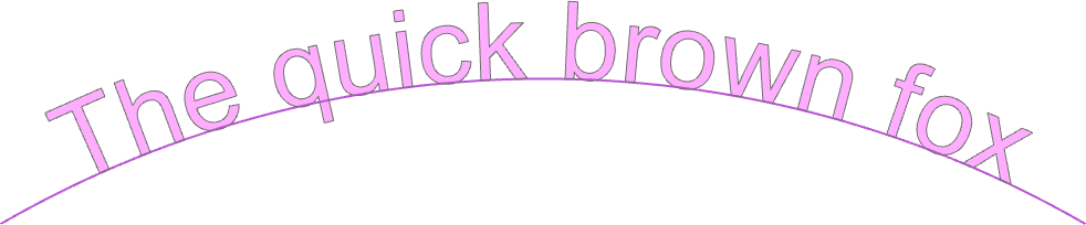
text = "The quick brown fox"
path = RadiusArc((-50, 0), (50, 0), 100)
Text(
    text,
    10,
    path=path,
    position_on_path=.5,
    text_align=(TextAlign.CENTER, TextAlign.BOTTOM)
)
Single Line Fonts
"singleline" is a special font referencing Relief SingleLine CAD.
Glyphs are represented as single lines rather than filled faces.
Text creates an outlined face by default. The outline width is controlled
by single_line_width. This operation is slow with many glyphs.
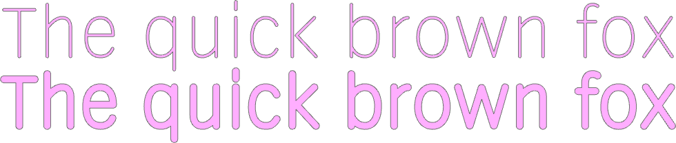
Text(text, 10, "singleline")
Text(text, 10, "singleline", single_line_width=1)
Use Compound.make_text() to create unoutlined single-line text.
Useful for routing, engraving, or drawing label paths.

Compound.make_text(text, 10, "singleline")
Common Issues
Missing Glyphs or Invalid Geometry
Modern variable-width fonts often contain glyphs with overlapping stroke
outlines, which produce invalid geometry. ocp_vscode ignores invalid
faces.
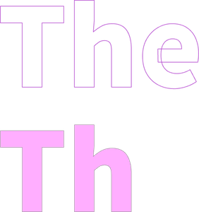
Text("The", 10, "Source Sans 3 Black")
FileNotFoundError
Ensure relative font_path specifications are relative to the current
working directory.
Custom Objects
All of the objects presented above are normal Python classes built on the
Base*Object classes. Users can use these same base classes to create their
own reusable objects that work like the core build123d objects in both Algebra
and Builder mode.
The base class is chosen from the dimensionality of the object being created:
Object being created |
Base class |
Builder |
|---|---|---|
3D solid or part |
||
2D face or sketch |
||
Single 1D edge |
||
Connected 1D wire |
||
General 1D curve |
A custom object usually follows the same pattern:
Create a class that inherits from the appropriate
Base*Object.Put the input parameters in the class
__init__method.Build the shape using normal build123d tools.
Pass the completed object to
super().__init__(..., mode=mode).
The Base*Object class handles the Builder integration. Intermediate objects
created inside the custom object are isolated from the caller’s Builder context,
so a helper Box, Circle, or Line used during construction doesn’t
leak into the user’s model. When the custom object is complete, it is published
once to the active Builder using the provided mode. Any active
Locations context and any Builder placements are
applied at publication time, just as they are for the built-in objects.
Each built-in base class also declares which Builder it applies to. For example,
BasePartObject applies to BuildPart and BaseSketchObject applies to
BuildSketch. If a custom object inherits from one of these base classes and
is used in the wrong Builder, build123d raises an error before the custom object
is constructed. This validation is provided by the inherited _applies_to
attribute; most custom objects don’t need to set it themselves unless they are
creating a new base class or intentionally changing the Builder compatibility.
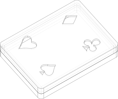
Here is an example of a custom sketch object specially created as part of the design of
this playing card storage box (see the playing_cards.py example):
class Club(BaseSketchObject):
    def __init__(
        self,
        height: float,
        rotation: float = 0,
        align: tuple[Align, Align] = (Align.CENTER, Align.CENTER),
        mode: Mode = Mode.ADD,
    ):
        with BuildSketch() as club:
            with BuildLine():
                l0 = Line((0, -188), (76, -188))
                b0 = Bezier(l0 @ 1, (61, -185), (33, -173), (17, -81))
                b1 = Bezier(b0 @ 1, (49, -128), (146, -145), (167, -67))
                b2 = Bezier(b1 @ 1, (187, 9), (94, 52), (32, 18))
                b3 = Bezier(b2 @ 1, (92, 57), (113, 188), (0, 188))
                mirror(about=Plane.YZ)
            make_face()
            scale(by=height / club.sketch.bounding_box().size.Y)
        super().__init__(obj=club.sketch, rotation=rotation, align=align, mode=mode)
Here the new custom object class is called Club and it’s a subclass of
BaseSketchObject because it creates a 2D sketch object.
The __init__ method contains the parameters used to instantiate the custom
object: height, rotation, align, and mode. Your objects may have
different parameters, but should usually include mode so they can be added
to, subtracted from, intersected with, or kept private in a Builder.
The middle of the method creates the object itself, in this case a sketch of the
club suit. The final line calls super().__init__ with the completed sketch
and passes through the rotation, align, and mode parameters handled
by BaseSketchObject.
That’s it. The Club object can now be used anywhere a
Circle would be used, with either the Algebra or
Builder API.