BuildPart
BuildPart is a python context manager that is used to create three dimensional objects - objects with the property of volume - that are typically finished parts.
The complete API for BuildPart is located at the end of this section.
Basic Functionality
The following is a simple BuildPart example:
length, width, thickness = 80.0, 60.0, 10.0
center_hole_dia = 22.0

with BuildPart() as ex2:
    Box(length, width, thickness)
    Cylinder(radius=center_hole_dia / 2, height=thickness, mode=Mode.SUBTRACT)
The with statement creates the BuildPart context manager with the
identifier ex2 (this code is the second of the introductory examples).
The objects and operations that are within the
scope (i.e. indented) of this context will contribute towards the object
being created by the context manager. For BuildPart, this object is
part and it’s referenced as ex2.part.
The first object in this example is a Box object which is used to create
a polyhedron with rectangular faces centered on the default Plane.XY.
The second object is a Cylinder that is subtracted from the box as directed
by the mode=Mode.SUBTRACT parameter thus creating a hole.

Implicit Parameters
The BuildPart context keeps track of pending objects such that they can be used implicitly - there are a couple things to consider when deciding how to proceed:
For sketches, the planes that they were constructed on is maintained in internal data structures such that operations like
extrude()will have a good reference for the extrude direction. One can pass a Face to extrude but it will then be forced to use the normal direction at the center of the Face as the extrude direction which unfortunately can be reversed in some circumstances.Implicit parameters save some typing but hide some functionality - users have to decide what works best for them.
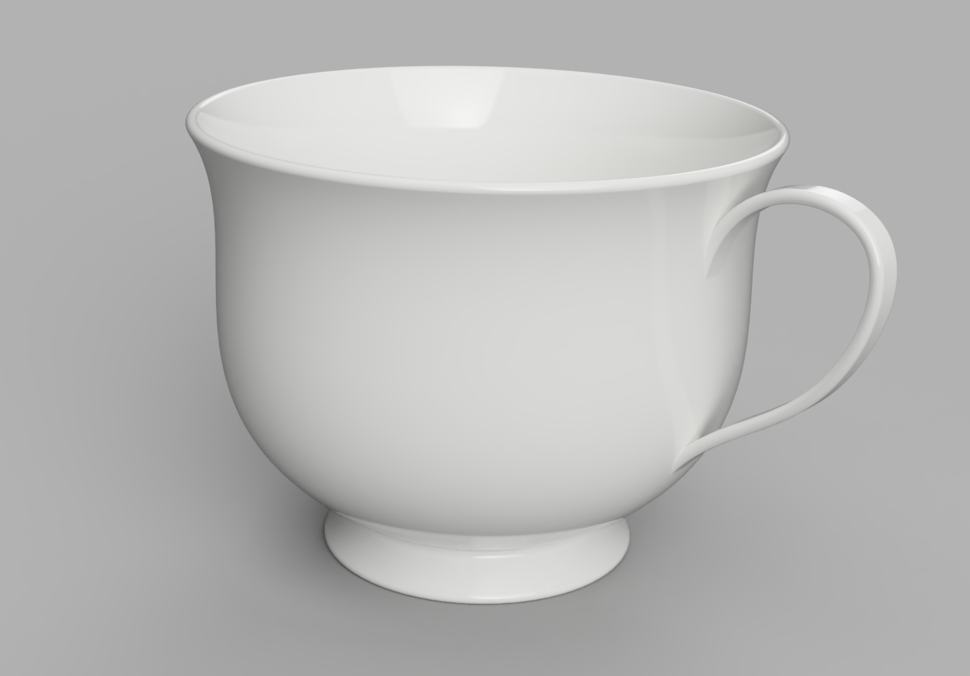
This tea cup example uses implicit parameters - note the sweep()
operation on the last line:
from build123d import *
from ocp_vscode import show

wall_thickness = 3 * MM
fillet_radius = wall_thickness * 0.49

with BuildPart() as tea_cup:
    # Create the bowl of the cup as a revolved cross section
    with BuildSketch(Plane.XZ) as bowl_section:
        with BuildLine():
            # Start & end points with control tangents
            s = Spline(
                (30 * MM, 10 * MM),
                (69 * MM, 105 * MM),
                tangents=((1, 0.5), (0.7, 1)),
                tangent_scalars=(1.75, 1),
            )
            # Lines to finish creating ½ the bowl shape
            Polyline(s @ 0, s @ 0 + (10 * MM, -10 * MM), (0, 0), (0, (s @ 1).Y), s @ 1)
        make_face()  # Create a filled 2D shape
    revolve(axis=Axis.Z)
    # Hollow out the bowl with openings on the top and bottom
    offset(amount=-wall_thickness, openings=tea_cup.faces().filter_by(GeomType.PLANE))
    # Add a bottom to the bowl
    with Locations((0, 0, (s @ 0).Y)):
        Cylinder(radius=(s @ 0).X, height=wall_thickness)
    # Smooth out all the edges
    fillet(tea_cup.edges(), radius=fillet_radius)

    # Determine where the handle contacts the bowl
    handle_intersections = [
        tea_cup.part.find_intersection_points(
            Axis(origin=(0, 0, vertical_offset), direction=(1, 0, 0))
        )[-1][0]
        for vertical_offset in [35 * MM, 80 * MM]
    ]
    # Create a path for handle creation
    with BuildLine(Plane.XZ) as handle_path:
        handle_points = [
            Plane.XZ.to_local_coords(point) for point in handle_intersections
        ]
        Spline(
            handle_points[0] - (wall_thickness / 2, 0),
            handle_points[0] + (35 * MM, 30 * MM),
            handle_points[0] + (40 * MM, 60 * MM),
            handle_points[1] - (wall_thickness / 2, 0),
            tangents=((1, 1.25), (-0.2, -1)),
        )
    # Align the cross section to the beginning of the path
    with BuildSketch(handle_path.line ^ 0) as handle_cross_section:
        RectangleRounded(wall_thickness, 8 * MM, fillet_radius)
    sweep()  # Sweep handle cross section along path

assert abs(tea_cup.part.volume - 130326) < 1

show(tea_cup, names=["tea cup"])
sweep() requires a 2D cross section - handle_cross_section -
and a path - handle_path - which are both passed implicitly.
Units
Parts created with build123d have no inherent units associated with them. However, when
exporting parts to external formats like STL or STEP the units are assumed to
be millimeters (mm). To be more explicit with units one can use the technique shown
in the above tea cup example where linear dimensions are followed by * MM which
multiplies the dimension by the MM scaling factor - in this case 1.
The following dimensional constants are pre-defined:
MM = 1
CM = 10 * MM
M = 1000 * MM
IN = 25.4 * MM
FT = 12 * IN
THOU = IN / 1000
Some export formats like DXF have the ability to explicitly set the units used.
Reference
- class BuildPart(*placements: ~build123d.topology.two_d.Face | ~build123d.geometry.Plane | ~build123d.geometry.Location, mode: ~build123d.build_enums.Mode = <Mode.ADD>)[source]
The BuildPart class is another subclass of Builder for building parts (objects with the property of volume) from sketches or 3D objects. It has an _obj property that returns the current part being built, and several pending lists for storing faces, edges, and planes that will be integrated into the final part later. The class overrides the _add_to_pending method of Builder.
- Parameters:
- build123d_type: ClassVar[str] = 'BuildPart'
- property location: Location | None
Builder’s location
- property part: Part | None
Get the placed part.
- property part_local: Part | None
Get the part in the Builder’s local construction coordinates.
- property pending_edges_as_wire: Wire
Return a wire representation of the pending edges